All ATS alignment turning stations are suitable for a
variety of samples and applications. Setup and
adjustment of a new sample is done in a short time.
The production of high-performance optics is
possible with an accuracy of < 1 µm for the centering
error, < 1 µm for the flange distance, < 1 µm for the
roundness and < 2 µm for the diameter of brass lens
mounts.
Streamlined processes, especially during subsequent
lens assembly, increase production productivity.
Automated alignment chuck
Reproducible manufacturing with a repeatability of
better than 2.5 µm
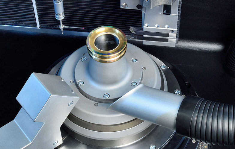
Easy to clean via integrated chip extraction
Suitable for cycle time optimized processing of large
batch sizes
Optional with hydrostatic spindle
Automated adjusting chuck
Great stiffness and thermal stability due to optimized
granite base
Reproducible manufacturing with a repeat accuracy of
better than 1.0 µm
 ATS 400
The ATS 400 is currently the largest alignment turning station in the ATS family. It was specially developed for the requirements of the semiconductor industry and is therefore designed for machining large and heavy lenses with the highest accuracy.
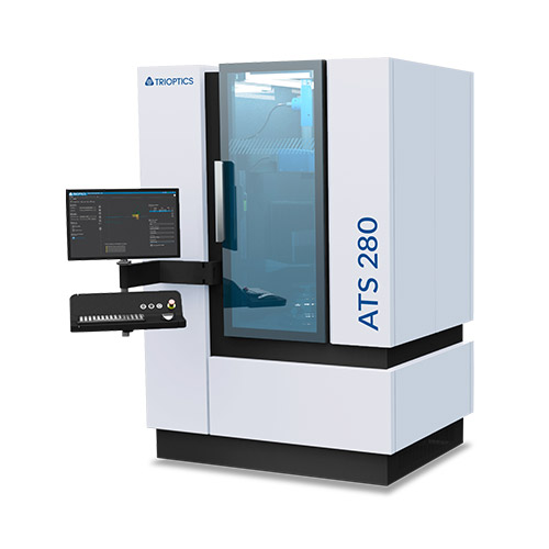
ATS 280
The ATS 280 was also an adaptation for the semiconductor industry. Larger cells can also be processed here. However, in order to make this possible on the still small footprint of the ATS 200, some options that were not required were omitted.
ATS 400
The ATS 400 is currently the largest alignment turning station in the ATS family. It was specially developed for the requirements of the semiconductor industry and is therefore designed for machining large and heavy lenses with the highest accuracy.
ATS 280
The ATS 280 was also an adaptation for the semiconductor industry. Larger cells can also be processed here. However, in order to make this possible on the still small footprint of the ATS 200, some options that were not required were omitted.
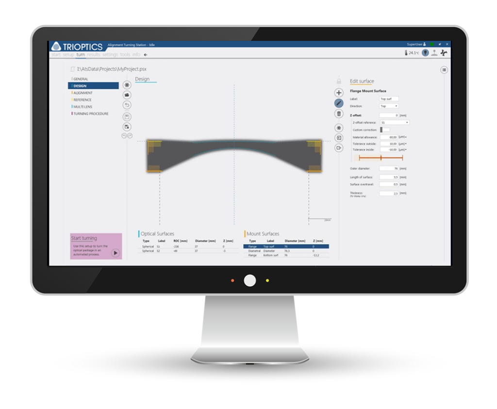
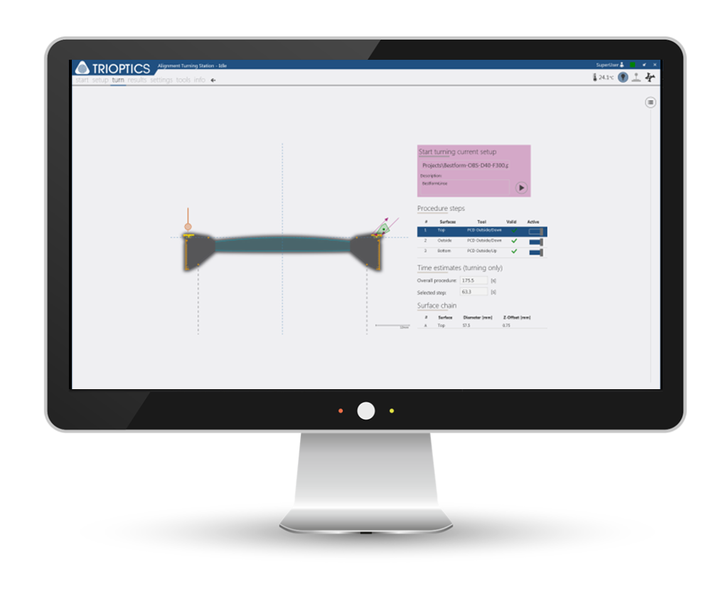
The ATS Control combines operation of the machine functions with the routines for measurement of
centering error and alignment. The user is guided step by step, both in setting up sample geometry
and carrying out the processing procedure. The software continually monitors the results of the
production process.


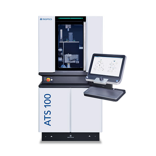
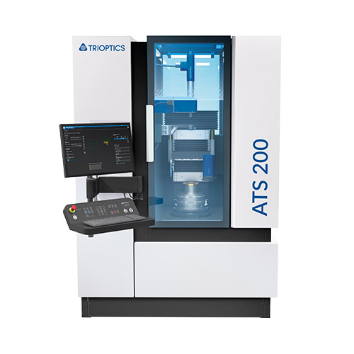
| Parameter | ATS 100 | ATS 200 | ATS 200 UP |
| Machine type | Mineral casting base | Granite frame | Granite frame |
| Spindle | Aerostatic | Aerostatic | Hydrostatic |
| Workpiece diameter | Up to 100 mm | Up to 200 mm | Up to 200 mm |
| Max. workpiece weight | 3kg | 5kg | 5kg |
| Workpiece material | brass, aluminium, NiP-Steel | brass, aluminium, NiP-Steel | brass, aluminium, NiP-Steel, invar, titan, steel |
| Production accuracy | Up to < 2.5 µm | Up tp < 1.0 µm | Up to < 0.5 µm |
| Dimensions (h x w x d) |
ca. 2.0 m x 1.0 m x 1.0 m | ca. 2.20 m 1.55 m x 1.10 m | ca. 2.20 m 1.55 m x 1.10 m |
| Weight | approx. 1,400 kg | approx. 2,500 kg | - |
| Type | Stand alone | Stand alone | Stand alone |
 Download Technical Data
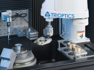
Alignment turning is the only method by which all relevant parameters of a mounted lens can be aligned, in particular the gap between two apex points and the contact surface.
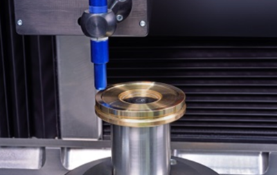
In addition, a large number of different cell sizes can be processed. And finally, high precision turning machines achieve excellent production accuracies of up to 0.5 µm. The alignment turning method is described in the figures below (Fig. 3). In alignment turning, first the lens cell is fixed in an adjustable alignment chuck with the lens in place. Then the position of the optical axis of the lens to the spindle axis is measured with the OptiCentric® system. Using this alignment chuck, the lens is then aligned so that its two centers of curvature are located as closely as possible to the axis of rotation of the spindle.
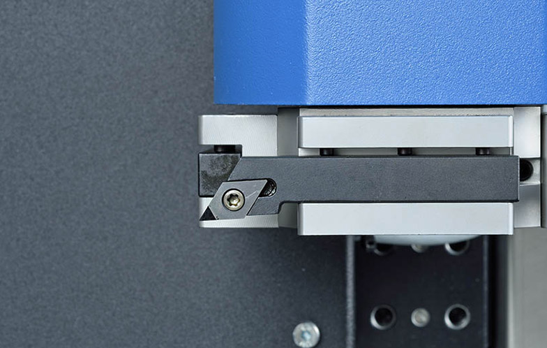
Then the spindle is rotated and the contact surfaces of the cell are machined with a sharp (diamond) turning tool, resulting in a precisely machined surface of the cell, aligned parallel to the spindle axis. In addition to the outer surface of the cell, it is also possible to machine the front and rear contact surface during the turning process. To do this the turning tool is moved perpendicular to the spindle axis instead of along the optical axis.
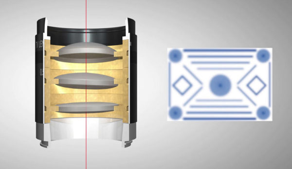
Fig.1: The optical axes do not coincide with the axis of the barrel; lens distances are not correct
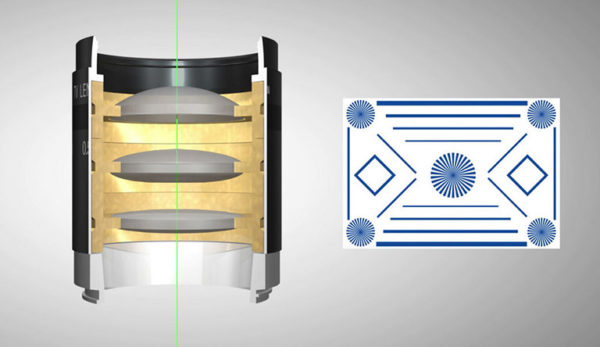
Fig.2: The optical axes and the axes of the barrel coincide, lens distances are correct
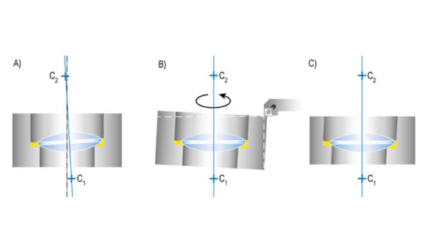
Fig. 3: The alignment turning process A) optical axis of the lens is determined, B) & C) cell is aligned to the optical axis of the lens, the edge of the cell is machined so that it is parallel to the optical axis
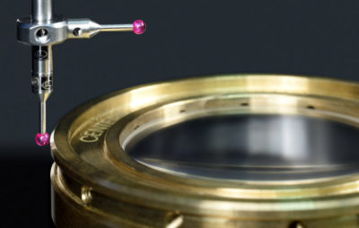
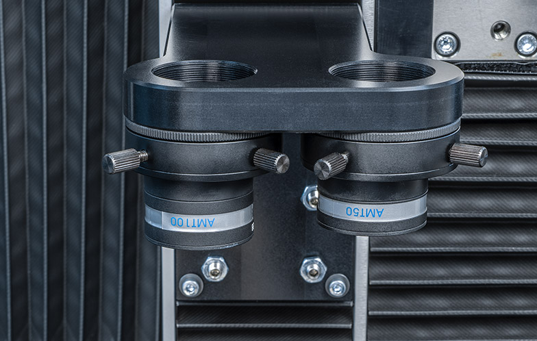
The lens is already fixed in the cell during the alignment turning process. This means that low-stress adhesives with very long curing times can be used for highly precise optics. Similarly, the lenses can be crimped or held by screw rings when the available adhesives are not suitable for the intended application. Since the lens has been aligned at the beginning of the process, the optical axis of the lens and the mechanical axis of the cell are precisely aligned when the cell is machined on a turning machine corresponding to the optical axis of the lens. In order to achieve high accuracy TRIOPTICS has integrated additional measurement technology into its alignment turning stations, alongside the high-resolution autocollimators. These include tactile and optical test systems that ensure a highly accurate measurement of the relevant mechanical parameters. This means the highest precision is achieved by a gradual machining process, in which the cell accuracy is checked after each machining step. The cells used in alignment turning do not need to meet exceptionally tight tolerances before machining. The cell offset only needs to be large enough to meet the required tolerance after machining.
The distance from the lens vertex to the upper contact surface can be manufactured with an accuracy of up to ±0.5 µm. Similarly, the diameter can be manufactured with an absolute accuracy of ±2 µm. The remaining centration error can be reduced to less than 0.5 µm by using a suitable alignment chuck. Moreover, a low coherent interferometer can be used to measure the center thickness on the machine, so that the contact surfaces can be manufactured with high precision with respect to each lens vertex. Multiple mounted lenses manufactured by alignment turning are then assembled to an objective lens. The method of machining in the micron range ensures that all lenses are aligned to each other. This allows mounted lenses to be assembled in a tube without further adjustment steps