The various CamTest systems can measure optical and opto- mechanical test parameters such as MTF, image plane tilt and rotation, as well as sensor parameters such as relative illumination or spectral response.
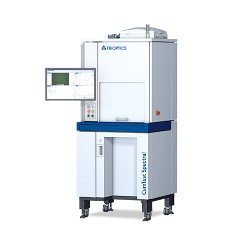
The product range covers all use cases for testing the image quality of camera modules. This results in four different types of measuring processes: CamTest MTF, CamTest Focus, CamTest Chart and CamTest Spectral.
In addition to the complete camera characterization, the measurement parameters are used for an inline calibration of the tested modules.
Testing of all essential image quality characteristics of
camera modules in just one system
Flexibility with regard to different camera types
Flexible low to mid volume production and R&D
Fully automated process
MTF, LSF, SFR, ESF
Image Plane Tilt, Defocus, DOF
Boresight Shift, Roll Angle
Optical Centre
Distortion, EFL
Defect Pixel, Particle, FPN
OECF, Dynamic Range, White Balance, SNR
Relative Illumination
Color Rendering, Crosstalk
Spectral Response
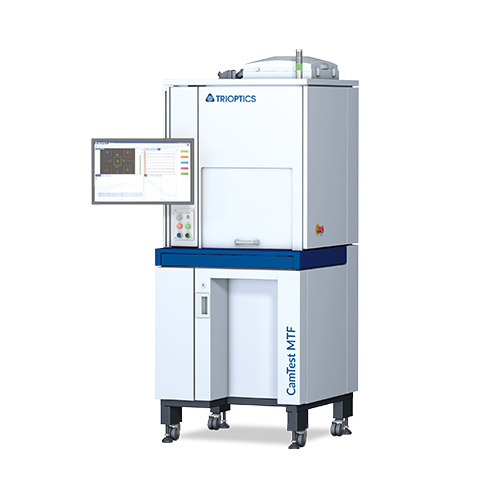
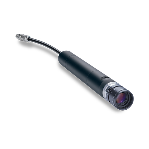
With this set-up, the MTF can be quickly and easily determined
Furthermore, also Line Spread Function, SFR and ESF can be measured
This method is escpecially suitable for a final quality check in high volume camera production.
the setup provides a field of view of +/-90°
variable object distance from finite to infinite in just one measurement setup
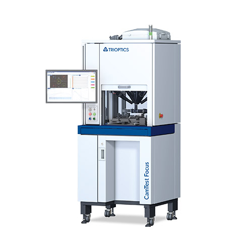
measurement of various parameters such as: MTF, SFR, through-focus MTF, image plane tilt, boresight shift, roll angle
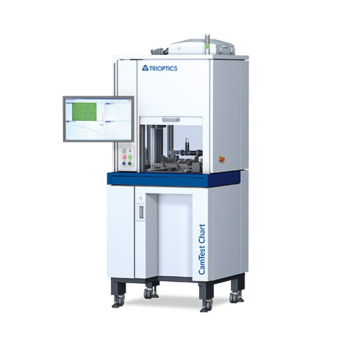
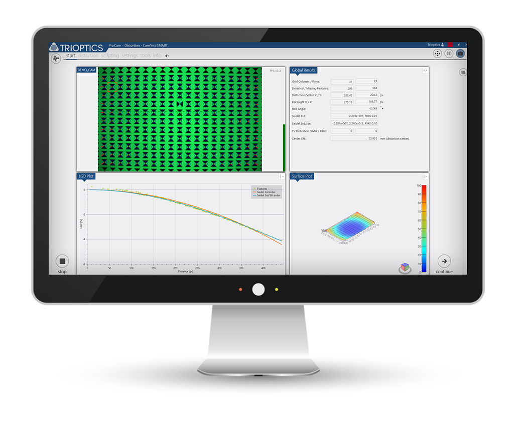
Measurement of: camera lens geometric distortion (LGD), TV distortion, camera boresight and optical center, camera EFL and FOV.
From the distortion measurement the distortion coeffecients (Seidel coefficients) are obtained used for the calibration of the camera module under test
Especially relevant for ADAS (Advanced Driver Assistance Systems)
The relay optic is available as an upgrade
Measurements of camera modules with up to 160° field of view
The sphere allows a light uniformity of more than 95 %
The setup is particularly well-suited for measuring parameters such as defect pixels, FPN, color rendering, OECF, relative illumination and dynamic range.
available for various wavelength ranges (VIS, NIR and LWIR)
can be used for many types of camera modules
ideal solution for comprehensive measurement tasks in the R&D environment
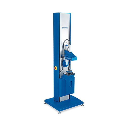
wide off-axis angle range of up to +/- 110°
Compact design for dense field of view (FOV) coverage
Infinite conjugate testing for very wide FOV cameras
For measurement of MTF/ SFR, through-focus MTF/ SFR, image plane tilt, camera boresight, focus setting and roll angle
High speed and high positioning repeatability
 Brochure CamTest ColMot
Long product lifetime
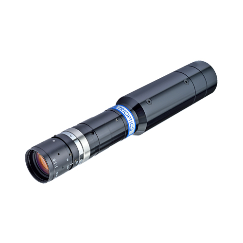
The most compact design for dense field of view (FOV) coverage
Highest speed for fast measurements and short cycle times
High positioning repeatability and accuracy
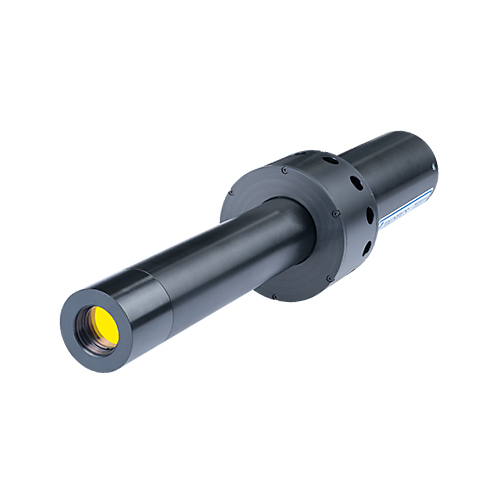
Making the invisible visible with the LWIR collimators in infrared technology
Wavelength range: 7 -12 μm
Effective focal length (EFL): 50 mm, 200 mm or 500 mm
5-axis Controller manages and monitors the lighting, the shutter and the fan

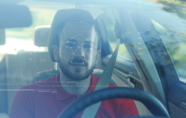
Image quality features (MTF)
Optomechanical properties: sensor position (tilt, rotation, defocusing)
Other optical parameters: distortion, relative illumination, focal length
Color characteristics: chromatic aberrations
Lens light reflection
| Parameter | CamTest R&D | CamTest MTF | CamTest Focus | CamTest Chart | CamTest Spectral | CamTest Smart |
| Field of view | Up to ±90° (up to ±110° after individual clarification) |
Up to ±70° diagonal field of view (up to ±90° after individual clarification) |
Up to ±70° diagonal field of view (up to ±90° after individual clarification) |
Up to ±35° diagonal field of view (up to ±50° after individual clarification) |
Up to ±70° diagonal field of view (up to ±80° after individual clarification) |
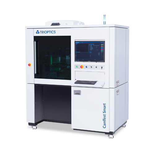
Depending on the instrument configuration and up to 3 possible integrated measuring chambers (MTF, Focus, Chart or Spectral) |
|
Standard illumination wavelength (others on request) |
White LED with PE-Filter RGB LED: 625 nm/520 nm/470 nm 940 nm & 850 nm |
White LED colour temperature 6500 K |
White LED colour temperature 6500 K |
Backlit LED green narrow spectrum |
Adjustable spectrum 420 nm … 780 nm |
|
|
Sample EFL (Effective Focal Length) |
1.8 mm … 16 mm 1) | 1 mm … 12 mm 1) | 1.8 mm … 12 mm 1) | 1 mm … 12 mm 1) | 1 mm … 12 mm 1) | |
| Object distance | 0.5 m to infinity | Infinity | 1000 mm … infinity | Finite / infinite | 1000 mm … infinity | |
| Typ. measurement time |
2 s … 1 min (Depending on the number of different parameters to be measured) |
< 2 s | < 15 s | < 5 s |
< 5 s particle & defect pixel, < 5 s shading, < 10 s OECF, < 15 s spectral response |
|
|
Sample diameter / Free aperture |
n.a. | n.a. / < 5 mm | n.a. / < 5 mm | n.a. / < 5 mm | 2 mm … 20 mm / n.a. | |
| Camera interface |
Software Development Kit provided enabling to connect customer camera with own framegrabber to all standard interfaces (either MIPI, analog or directly to e. g. USB, FireWire, CamLink, GigE). |
|||||
| Type | Stand alone | |||||
| Dimensions (h x w x d) | 2,000 mm x 800 mm x 1,500 mm |
2,150 mm x 1,120 mm x 875 mm | 2,159 mm x 1,740 mm x 1,226 mm | |||
| Weight (approx.) | 300 kg | Up to 350 kg | 750 kg | |||
| Power consumption | max. 1300 W | typ. 100 W … 500 W | 300 W … 1000 W | |||
| Voltage | 100 … 130 VAC oder 220 … 230 VAC |
100 … 130 VAC or 220 … 230 VAC | ||||
| Compressed air | - | 5 bar … 7 bar (optional for sample fixation) | ||||
| External Communication Interface | TCP - IP | TCP - IP OPC - UA |
||||
 Download Technical Data
Image quality testing of complete cameras and assembled camera modules is done by imaging a suitable target using the camera module under test and evaluating the quality of the reproduction of the target. New approaches for testing methodologies are required to keep up with technological developments and economic pressure. Most of these can also be used in a similar fashion for all other camera testing applications, from high-end scientific to thermal imaging surveillance cameras.
Most consumer-type camera modules are integrated into devices such as smartphones and webcams and use relatively short-focal-length (1 to 5 mm), wide-field-of-view optics and either CCD or CMOS color sensors.
The parameters typically extracted during testing of such a module can broadly be classified into five categories: image quality via the modulation transfer function, the spatial frequency response; properties of the optical system (e.g., distortion, relative illumination); optomechanical properties (e.g., relative alignment of the optics and the sensor or autofocus precision); color properties (e.g., color rendition, white balance); and sensor properties (e.g., dynamic range, linearity, noise, bad pixels). For modules incorporating flash capabilities, the alignment, illumination profile and intensity of the flash unit can be characterized as well. We will focus on the first three topics .
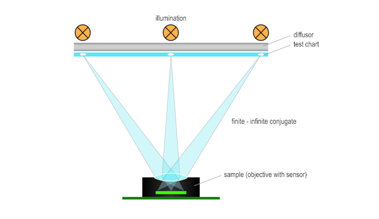
Although most camera modules are designed to be used with the object at a larger distance (infinite conjugate), conventional testing techniques usually place a test target with various patterns – typically a test chart – at a shorter distance (finite conjugate) from the module.
Today, testing with test charts in finite distance is standard, done by image analysis software in real time.
Figure 1 shows a schematic representation of a test chart system in finite configuration. The device under test (DUT) is placed in front of an illuminated chart with different markers and patterns on it. An image is then taken with the DUT, and software algorithms analyze the position and shape of the markers, and extract the performance parameters of the camera module.
A modified version of this setup incorporates a relay lens in between sample and chart to create a virtual image of the chart as seen from infinite distance. This approach usually requires a custom, high-quality relay lens, especially for larger-field-of-view applications and broadband (e.g., daylight) illumination, which can make such a setup complex and commercially unviable. This solution should be used only if infinity conjugate measurement and a more complex chart evaluation are required.
This test chart technology is relatively easy to deploy and combines a high density of measurement points with the ability to use different types of markers and patterns on different field positions of a single chart. It is typically used for sensor resolutions of up to 13 MP and testing in finite or close-to-infinite distances. However, because of recent advances in manufacturing technology, this technology reaches its limits as the industry moves to sensor resolutions of 13 MP and higher, which tightens the requirements on optics and the alignment of the individual components of the module.
Common precision and repeatability bottlenecks include the need for high homogeneity of the illumination over a large area, edge contrast and precision of the patterns on the test charts, and the required reproducible spectral distribution lighting, which is usually done with LEDs.
The size of the test instrument is another important factor in a production environment: For the wide-angle, large-field-of-view optics typically found in consumer camera modules, a large test chart is required. The larger the angular field of view, the larger the test chart must be for a given finite object distance, which cannot be set too small for infinity-set fixed-focus objectives. The situation is similar for modules that have a focusing capability – in this case, shorter object distances can be used, but the setup does not properly reflect the final application. For large test charts, the corresponding large instrument requires more precious factory floor space.
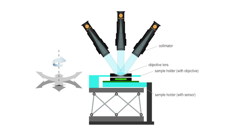
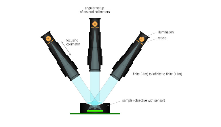
An alternative approach for testing camera modules with larger object distances between about 1 m and infinity is to use a set of collimators as target projectors where each measurement point on the image sensor is provided by a dedicated collimator. A collimator consists of an illuminated target structure (the reticle) in the focal plane of an objective lens. The collimator projects the target virtually onto the DUT (Figure 2). The collimators can be either fixed-focus with preset infinity or finite object distances, or they can be motorized for variable object distances.
The collimators are arranged in space so that the optical axes meet at the entrance pupil of the DUT. Different off-axis angles then correspond to different image positions on the DUT sensor, with on-axis being the center position on the sensor.Although this setup is more complex than a test chart setup, it offers several advantages and higher flexibility for testing at different object distances.
Figure 3 shows a typical collimator arrangement with nine collimators, all pointing into the entrance pupil of the DUT below (not shown). The spherical dome support allows the adjustment of the collimators to different object angles
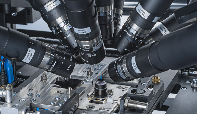
It can be used as a “true” infinite setup, with the DUT being tested under the same conditions as in the final application. This setup is quite insensitive to the actual positioning of the collimators, as the field positions are determined only by the angles between the collimators.
The test chamber is compact, with the outer dimensions independent of the DUT field of view, so it uses less factory floor and is easier to manage. In fact, the mechanically closest distance of the collimators should be used.
It is less sensitive to stray light, and the reticle illumination can be better controlled – which, in turn, leads to better repeatability.
By using motorized collimators that can be focused, arbitrary object distances from approximately 1 m to infinity can be generated. This makes it possible to test the focusing of fixed- and autofocus modules. It is further important for the high-precision active alignment technology.
Besides the setups for measurement of image quality and optomechanical parameters discussed, other parameters are typically characterized for camera modules: These relate to color (e.g., white balance, color rendition, spectral sensitivity, etc.); sensor characteristics (linearity, sensitivity, image noise, opto-electronic coversion function, bad pixels, etc.); or additional optical parameters such as distortion or veiling glare
The image acquisition and transfer time for most camera modules is short, so the data obtained from the DUT also can be used in production to proactively and automatically align the optics and sensor to each other in a real-time, closed-loop process so that the combination delivers the highest possible performance. Besides the simple three-axis alignment for focusing (Z) and centering (X-Y) of the sensor, rotation and, especially, sensor tilt relative to the image plane of the optics can be adjusted (Figure 4). The tilt adjustment becomes increasingly important for high-performance, high-resolution modules with short depth of focus to reach the required image quality. As sensor resolution increases and the required tolerances become smaller, the industry is forced to use automatic alignment systems instead of further reducing manufacturing tolerances.
Depending on the application, either a collimator arrangement or a finite test chart is used to provide the required information for the multiaxis active alignment system. To fix the achieved camera alignment, a glue dispenser with UV light curing can be embedded into the system, making the instrument a fully automated fabrication station for camera modules.